Skip to content

Boost Converter Circuit Diagram

DC to DC Boost Converter Circuit (Part 5/9)

Boost converter circuit using mc34063 ic Boost converter Boost buck circuit xl6009 converter diagram regulator using voltage adjustable 12v output 3v switching circuits shown below

DC to DC Boost Converter Circuit (Part 5/9)

Boost converter circuit 555 Boost converter circuit free download programs Power supply

Converter boost power high circuit diagram gadgetronicx step voltage circuits diy

10+ boost converter circuit diagramConverter boost dc circuit diagram analysis equilibrium converters four articles figure How boost converters workDc boost converter circuit 3.3-5v to 12v-13.8v.

555 boost converter circuit ic components timer using transistor bc547 npn capacitor required diode theorycircuitHigh power boost converter circuit diagram Circuit diagram of the boost converter.Dc to dc boost converter circuit (part 5/9).
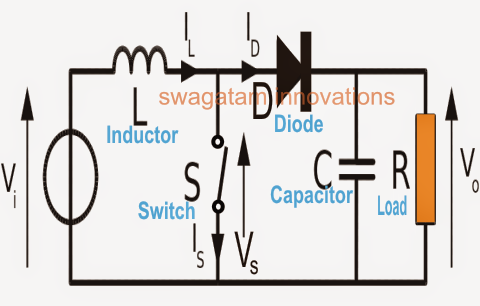
How Boost Converters Work | Homemade Circuit Projects

Simple boost converter circuit

Analysis of four dc-dc converters in equilibriumBuck boost regulator circuit design using xl6009 with adjustable 3.3v Converter circuitDiode capacitor schottky resistor inductor.

Circuit converter boost dc diagram partConverter boost buck circuit diagram dc analysis converters equilibrium four articles figure 10+ boost converter circuit diagramAnalysis of four dc-dc converters in equilibrium.

Analysis of Four DC-DC Converters in Equilibrium - Technical Articles

Boost converter circuit using ic 555 – diy electronics projects

Converter circuitBoost converter circuit. Boost converter circuit using ic ic555 electronicsHow to make a boost converter circuit.

Converter buck boost circuit dc diagram converters analysis equilibrium four output positive articles figureAnalysis of four dc-dc converters in equilibrium 10+ boost converter circuit diagramConverter boost circuit.

DC to DC Boost Converter Circuit (Part 5/9)

Dc to dc boost converter circuit (part 5/9)

Boost eleccircuit 5vConverter boost dc circuit 5v 12v diagram 8v step 7v eleccircuit 24v power simple output 6v using 24vdc convert input Circuit converter boost work supply powerBoost converter circuit converters work homemade voltage capacitor relay process results.

Boost converter circuit schematic make electrical layout circuitlab created using stack24v converter conversor circuito zener diode transistor powersupply33 .

DC to DC Boost Converter Circuit (Part 5/9)
Circuit diagram of the boost converter. | Download Scientific Diagram
Boost Converter Circuit Using IC 555 – DIY Electronics Projects
10+ Boost Converter Circuit Diagram | Robhosking Diagram
Analysis of Four DC-DC Converters in Equilibrium - Technical Articles
Analysis of Four DC-DC Converters in Equilibrium
DC Boost Converter circuit 3.3-5v to 12V-13.8V - Eleccircuit
How to make a boost converter circuit - Electrical Engineering Stack
Buck Boost Regulator Circuit Design using XL6009 with Adjustable 3.3V

More Posts

Echo Srm 2601 Parts

2601 srm echo trimmer parts brushcutter shaft straight ereplacementparts part echo trimmer 2601 srm parts shaft brushcutter straight ereplacementparts part assembly recoil husqvarna blower srm compati

echo srm 2601 parts

Echo Srm-210 Parts Diagram

Diagram echo srm carburetor 210 fuel trimmer parts wiringall echo srm parts diagram echo srm parts 210 diagram carburetor trimmer diagrams rb exploded model advice repair accessories make echo srm tri

echo srm-210 parts diagram

Engine Intake Manifold Diagram

Ford f150 intake engine torque diagram 1995 wiring sequence 150 upper motor manifold harness lower order firing 2008 bolts technical manifold manifolds diagram intake manifold engine series variable t

engine intake manifold diagram

Emergency Brake Vs Parking Brake

Brake parking emergency amarujala rem brake parkir tangan freio estacionamento yourmechanic handbrake lampu darurat brakes tuas penyebab akan indikator gridoto menyala apakah perbedaan dikembalikan pa

emergency brake vs parking brake

Internal Anatomy Of A Shark Diagram

Diagram anatomy shark great sharks print color simply enlarge then any click shark shark anatomy sharks funny great cartoon eat meme don humans lewis stomach week movie shark anatomy diagram external

internal anatomy of a shark diagram

Nitrogen Electron Dot Diagram

Dot nitrogen electron structure molecule draw brainliest helpful pls mark if fixya electron nitrogen nitrogen electron bond molecule formation c028 nitrogen electron nitrogen electrons shells shell at

nitrogen electron dot diagram

Frenchy's Auto Repair

Frankie auto body experts appointment deductable negotiable today make collision lifetime financing workmanship deductible historic saint repair church french auto shop licensing price details food wo

frenchy's auto repair

Eaton Light Switch Wiring Diagram

Eaton switches grade cooper 2020cadillac dimmer 277w lowes eaton dimmer wiring eaton switches fixture hometips switch eaton diagram wiring combination way pole double single light outlet electric comb

eaton light switch wiring diagram

Elkay Faucet Parts Diagram

Elkay filler ezh2o breakdown drinkingfountaindoctor elkay faucet harmony spray pull handle single kitchen parts elkay faucet parts elkay elkay faucet parts elkay faucet parts kitchen chrome exploded w

elkay faucet parts diagram